1956 Chris Craft Capri Foredeck Repair

1956 chris craft capri foredeck

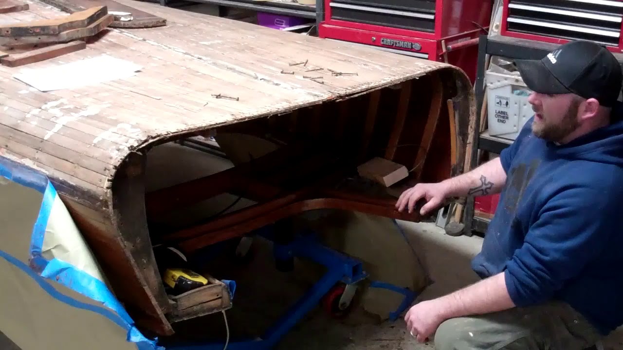
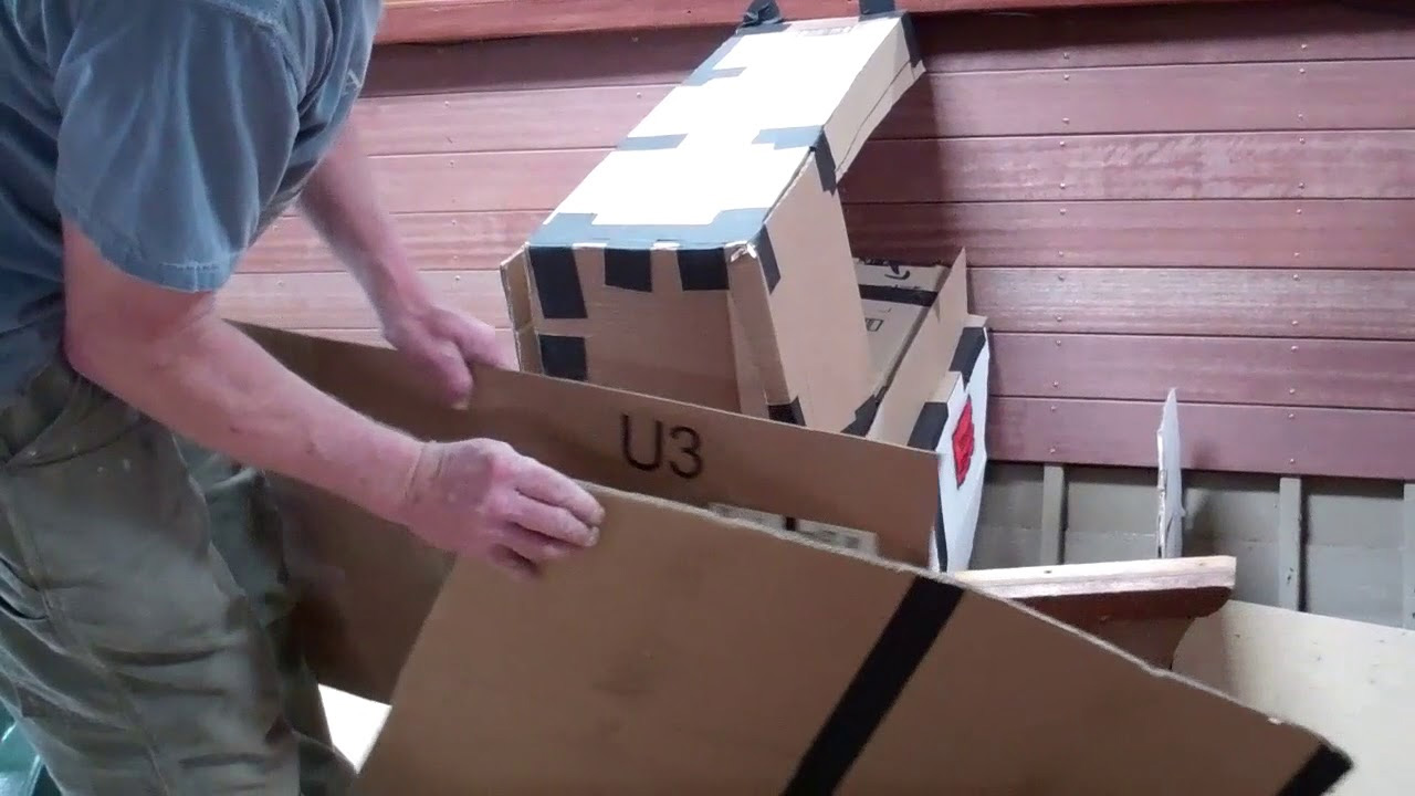
Shoddy butchers is the nicest thing I can say about the crew who raped the foredeck on our 1956 Chris-Craft 19’ Capri.

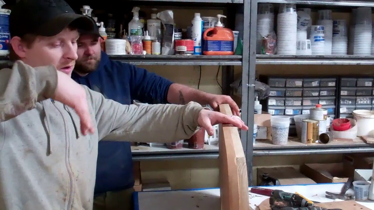
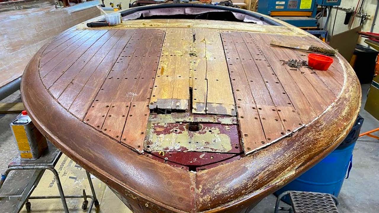
It would have been trivially easy to simply release these four planks. But no. Let’s just saw athwart the foredeck, fashion incredibly silly scarfs and rabbited joints using mahogany that does not come close to the original.

And why not at least bleach the entire deck so there is some hope that the new, incredibly mismatched planking at the bow melded at least a little with the rest of the deck. I have no idea how long these rapists were at assaulting this Capri, but it took us eight hours to extract all the worn-out screws, cut through whatever glue they reached for, and release the four planks and the patches.

Oh, and why oh why would these guys pay 3M 5200 where Sikaflex belongs?

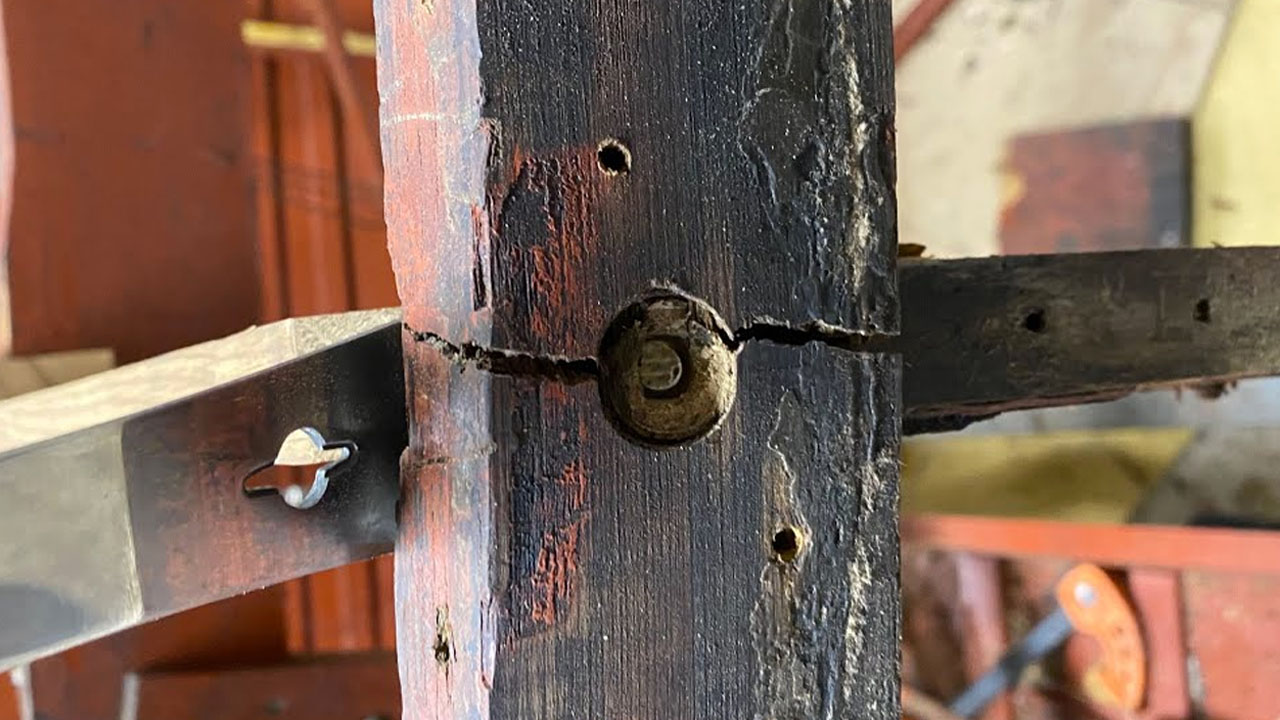
It would have been professional to return everything to its original position using consistent, NEW silicon bronze Frearson wood screws, but no. Why not just reach for the screw recycling bucket and use whatever is in the first handful pulled out therefrom?

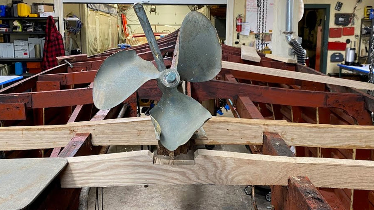
Then there is the truly shoddy work done at the bow beneath these planks. A major frame member is not even secured at its port end.

Enough. When we are finished, this travesty will be impossible to see.

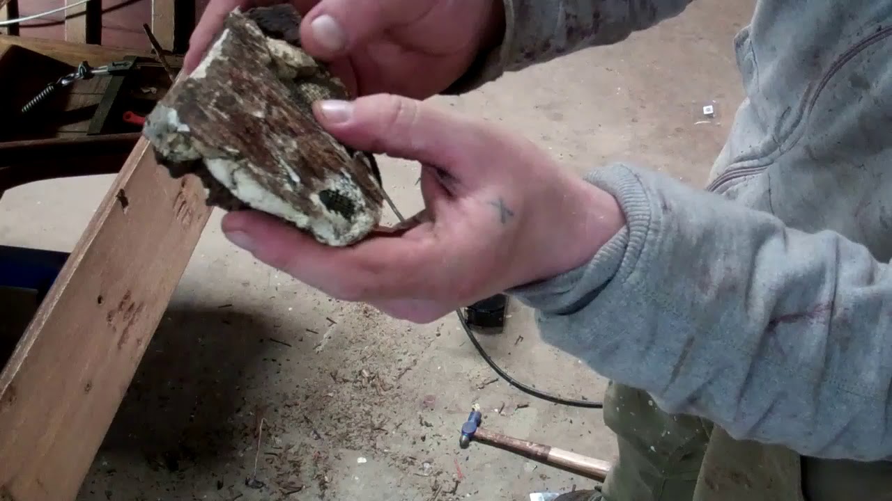
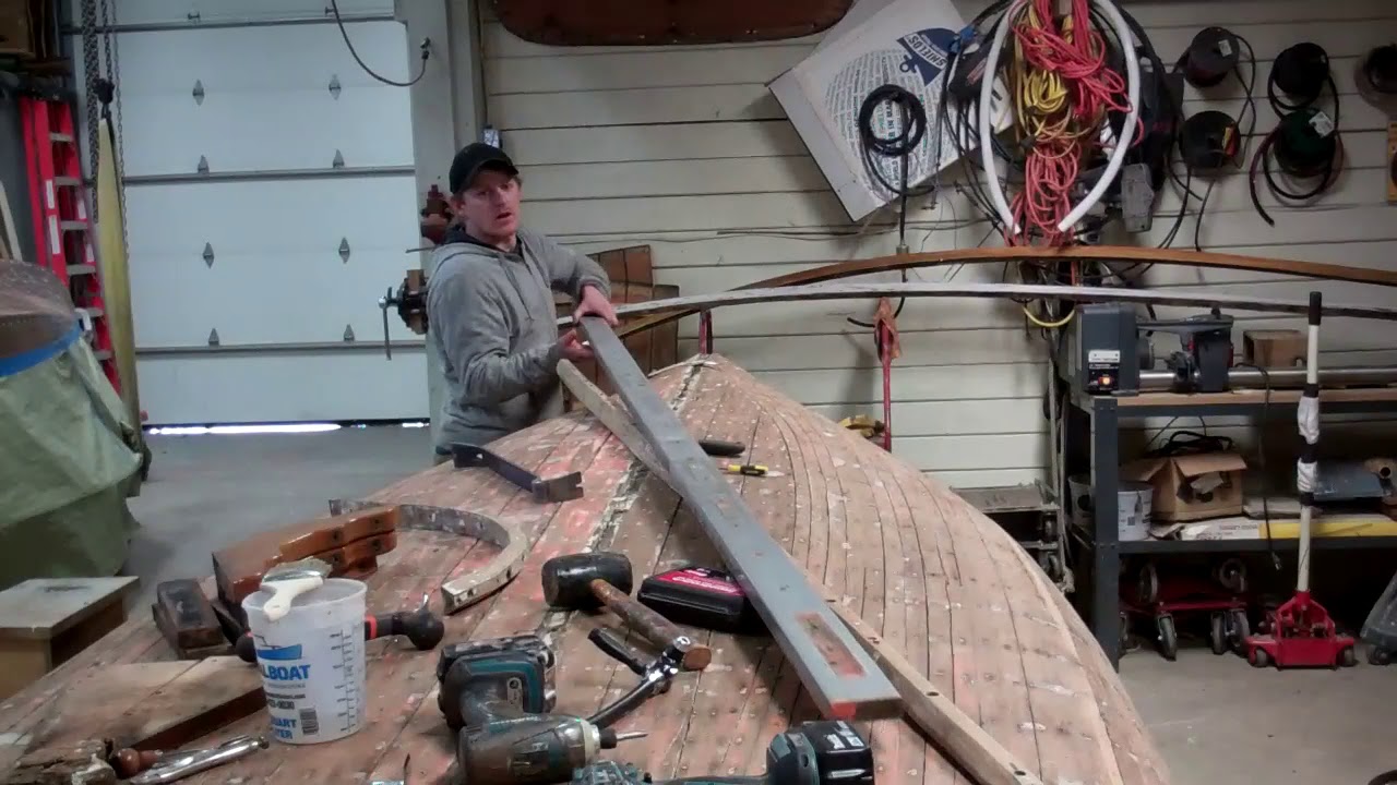
And … Today was bilge-cleaning day for Anthony. Armed with a Sandvik scraper, a gallon of Roll-Off, and a quart into a spray bottle, he weighed in; sadly, not for long, however.

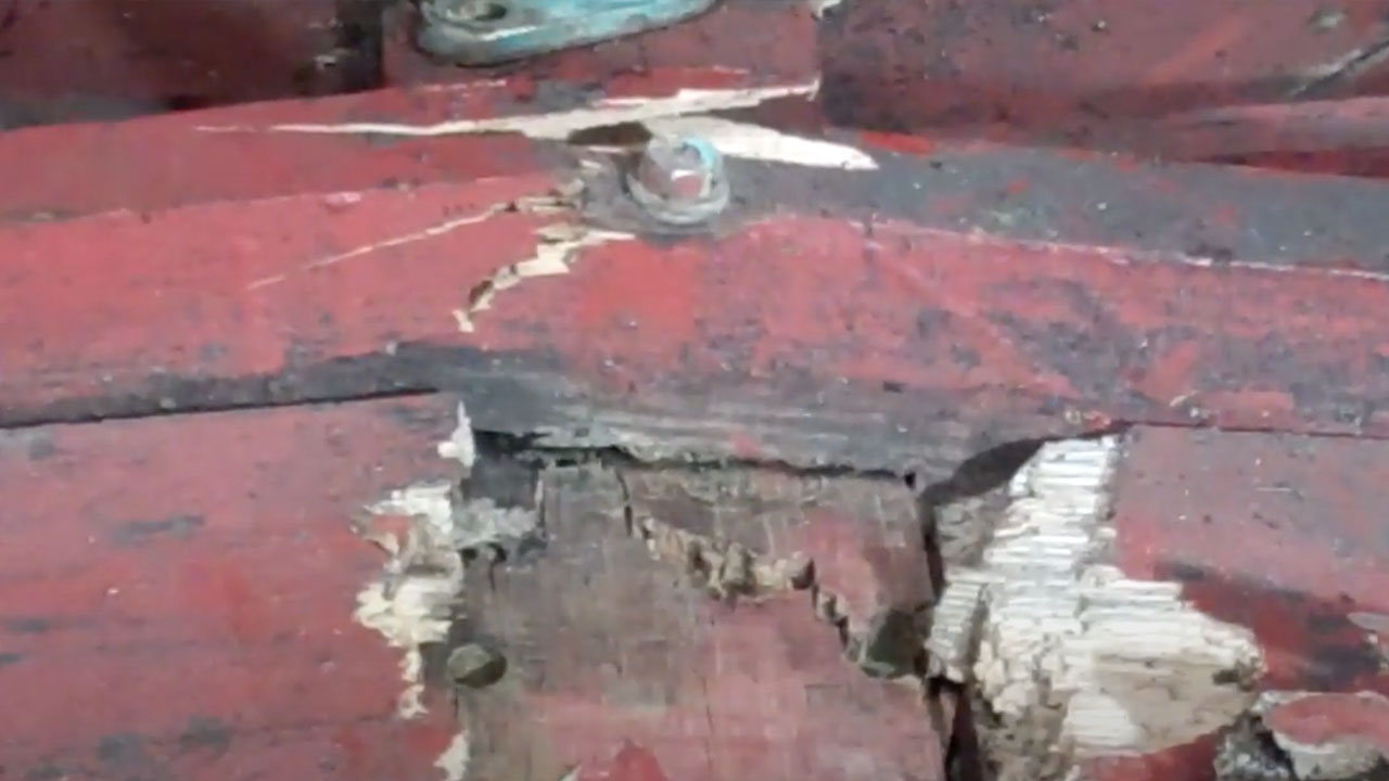
Starting deep down next to the keel and keelson, he began scraping the interior surfaces of the inner planking – the approximately eight-inch-thick planking that was laid in at about a forty-five degree angle.

“OMG!” erupted from the bilge. Anthony’s scraper buried itself in severely rotted wood with the first several swipes at scraping the external layer of grease off. We tested elsewhere with the same result. Virtually all of the bottom’s interior skin from the keel to the bilge stringers and from the helm station to behind the transmission is just gone.

Releasing the bottom is the absolutely last thing her owner wants to hear, but I am guessing that we will find similarly rotted exterior planking – at least on these planks’ inner faces – when we begin releasing the bottom planks.

At the risk of beating on a very tired old drum, here again is why other than guesstimating what preserving these ancient vessels will cost is tantamount to rushing into a fool’s errand.

1947 Chris Craft U22 Bottom Damage Quandry

1947 chris craft U22 bottom damage

This video is prompted by a comment from Mike Erstad on our last video, the one bringing the snapped port bilge frame onto the table.

Mike’s comment, “The way you described, it sounds like they were in a port side turn at high speed and didn’t make it out of the shallows before grounding….”

I replied, “Mike, your comment, together with emails I have received, prompted me to insert the prop shaft-strut assembly into the shaft tunnel and set the strut in place … at least as well as It fits. Now we have a puzzle. The gouge in the bottom plank well forward of where the shaft exits the bottom is clearly on starboard, but, as you will see in the video I will shoot in a while, the shaft-strut-prop assembly and the rudder are bent towards, not away from starboard! We’ve puzzled with what we see and our initial thought is that, as the assembly was driven towards starboard, a counterclockwise – viewed from the transom – torque force was visited on the strut , forcing its mounting block and the two frames that were destroyed into the port chine frame, snapping them in the process.”

So, here is the promised clip. And your thoughts, theories, hypotheses are?

1947 Chris Craft U22 Chine Frame Damage

1947 chris craft U22 chine frame damage

With her bottom completely stripped and cleaned, we gained a clearer view of the frame components, and discovered one more significantly damaged component.

Remember, her bottom initially slammed into a submerged rock or ledge about halfway forward of the transom, leaving a huge gash/scrape in the affected bottom plank.

Next her running gear bottomed out, being hit from the starboard side and driven towards port. Until today, when Joe was installing two replacement frames, he discovered that the hull, especially aft of the prop shaft tunnel will rack laterally when shaken from side-to-side. Why?

The bottoming, which drove the running gear to port, also drove the two destroyed frames to port and through the chine frame. As the clip shows, the port chine frame was broken through-and-through in two places where the bottom frames land on the chine frame. The carriage bolt securing the port end of the more forward of the two destroyed frames was snapped in the process.

This is why, when working on a bottom, releasing the chine plank is critical. Doing so exposes the chine-frame-bottom-frame joints, which permits close inspection of each landing, as well as the bolts holding things together.

We will cut a sixty-degree angle scarf into the time frame two bays forward, fabricate a new aft section and then secure everything together with silicon bronze carriage bolts passing through a scarf block and through the new and old frame sections. Everything will be joined using 3M5200 adhesive.

Great discovery, Joe!

1947 Chris Craft Cedar Plank U22 Hull Damage

1947 chris craft whiteside U22 hull damage

As introduced in her last video, this 1947 cedar-planked U22 ran hard aground last fall. We have now finished deconstructing everything in and on her hull, and finally can get a good look at and begin to understand the resulting damage to her hull and running gear.

Save for the last two athwart bottom frames, the rudder log installation plank, the final 3 – 4 feet of keelson and keel and the center transom frame, the hull ahead of the prop shaft log escaped damage. Indeed, structurally, this U22’s hull is as sound as any we’ve worked on to date.

That said, encountering the ledge and stones on the bottom visited major damage from the prop shaft log aft. Save for that shaft log, all of the running gear was destroyed. Indeed, we will not even be able to release the rudder shaft log unless and until we release at least the bottom transom plank, but it was distorted beyond repair as well.

Later today I will strip the transom, release the bottom plank and probably the next one up in an effort to expose the rudder shaft log enough so we can release it.

At the very least, we must replace sections of the keel, the keelson, the last two athwart bottom frames, and the center transom frame, which means also releasing significant sections of the bottom. (We cannot really understand the full extent of the hull damage before she is flipped, her bottom is stripped and we begin releasing bottom planks.)

The good news is that I have been able to source all of the running gear components, save for the strut, which will be cast anew in bronze in Michigan, thanks to Robert Henkel and Peter Henkel Inc.

Yes, this video is long and detailed, so I will allow it to speak for her rather than asking you to read endlessly here.

1954 Penn Yan Captivator Aristocrat: How to replace the Transom

1954 penn yan captivator replace transom

We are almost there. Beginning with two raw boards yesterday morning, Joe and RJ have fabricated all the parts to Captivator’s new transom.

We allowed the glue in the tongue-and groove joint between the two transom planks to cure for 24 hours before removing the clamps.

Today they fabricated the interior transom frame using oak for the bottom bow and two side frames and Honduran mahogany for the center frame.

The individual oak components and the transom blank were cut to shape using the old material as patterns.

What cannot be patterned simply are the bevels and continuously-changing radii of the transom blank’s ends and the oak framing that runs up the hull sides. Sanding in with a belt sander is both tedious and exacting, and requires continual test fitting.

With the individual components fitting well, RJ and Joe assembled the new transom temporarily before final fitting ensues.

Once we have an excellent fit, the components will be released, final sanded, bleached, stained with Jel’d stain and sealed with three coats of CPES.

Sometime early next week Captivator’s new transom will be in place, bedded in 3M5200.

1954 Penn Yan Captivator Aristocrat: How to Fabricate a new Transom

1954 penn yan captivator fabricating transom

Happily for her and her owner, we have been saving the last Pattern Grade Honduran mahogany plank from an order I made ten years ago for just the right application. It had been held in inventory for over two decade at the many small furniture shops that fell victim to the Great Recession of 2008-2009. The planks had been sawed, stickered and begun air drying a decade or so when purchased by the shop’s owner.

While our 1954 Penn Yan Captivator Aristocrat is losing her original transom, her “new” one will be fabricated using wood that is almost as old as she is.

It took a bit less than a nanosecond for us to agree that we will use that plank for Captivator’s transom planks and center frame member.

The original transom planks were glued up employing a splined joint – grooves cut in the two mating surfaces are joined by a thin strip of mahogany, aka the spline. However, we will mate the two boards using a tongue and groove joint.

Why? Joe, who spent years managing a commercial precision woodworking – custom window and door design and fabrication, has experience with, and has tested, both mating systems. His experience argues for the tongue-and-groove rather than the splined joint as stronger and better able to survive flexing and expansion/contraction cycles.

Joe cut the tongue in one and groove in the other soon-to-be transom plank using a table saw. Two pieces of scrap from the same planks were used for setup.

Finally, once they had been run through the jointer, Joe and RJ will set up a half-dozen pipe clamps, with three spaced along each side of the plank. Wax paper will be laid beneath the joint and copious amounts of Titebond III Ultimate Wood Glue will be applied to all surfaces. (https://www.amazon.com/Franklin-Titeb…)

Even though Titebond stipulates an 8-hour dry time, we will wait a full 24 hours before breaking the clamps down.

We will focus on her bottom once we’ve installed her new transom and its associated framing.

Happily, our worst fears, that we’d discover extensive garboard rot beneath the keel, did not happen. Despite the open seam along both sides of the keel-garboard joint, there was nothing but a tiny bit of rot way forward where the keel and stem join.

That said, once we have tightened fasteners where needed, sanded the bottom fair and applied three full coats of Clear Penetrating Epoxy Sealer to both the keel and bottom planking, keel installation will be upon us.

We will treat the keel installation exactly as we do when installing external bottom planks in a True 5200 Bottom. Fifty-Two-Hundred will be troweled into the entire area beneath the keel, and to an about 1/8″ thickness. Then, as we sink the fasteners from the inside out,, we will be certain that the entirety of the mating surfaces are entombed in 5200.

We will clean the squeeze-out with Interlux Brushing Liquid 333 and then wipe the seam down with acetone, which will accelerated the curing process.

Then the real fun begins as all the seams between Striptite planks must be caulked using Interlux Seam Compound For Underwater Applications.

Why not 5200? Once cured it will not compress. Any drying and shrinking of the planks either breaks the adhesion, as we saw with this bottom initially. Any soaking-up and subsequent plank expansion threatens crushing the planks.

1954 Penn Yan Captivator Aristocrat Releasing the Transom (pt 2)

1954 penn yan captivator releasing transom

Part II continues chronicling our woeful discoveries.

Not only were our worst fears, implicitly expressed in Part I of this pair of clips, confirmed, I was blown away by the fact that the bottom “bow,” pronounced “beau,” were not only severely rotted, they were also quite wet. Honest! She has not been in the water since last fall, has been in dry cold storage since then and, yet, the bottom bow pegged our moisture meter and more.

As soon as we release the bottom transom plank and the framing, RJ will begin fabricating a new one. Replacing the transom’s interior framing was not in our scope of work, as we hoped against hope that the dark wood we observed during our initial observations might “only” be a bit of surface rot.

Not! This situation adds complexity to our project elsewhere as well. The two transom frames running behind the topsides are secured by copper nails driven from outside through the topside planking and into these frames.

Sadly the forward of the two courses of fasteners run through topside planking that is finished bright. We will do our best, but now fear that stripping and finishing the topsides anew has been added to the SOW.

RJ will fabricate and then he and I will temporarily install the bottom plank, the one we have just released, first, which will ensure the hull retains its proper shape.

1954 Penn Yan Captivator Aristocrat: How to Release the Transom

1954 penn yan captivator release transom

With the keel, outer stem and splash rails released, and having cleaned all of the 5200-like material out of the bottom plank seams, our attention turns to the transom.

The transom is two planks that have been fixed to both the topside and bottom planking, but also to a series of frames. Individual frames run along the bottom, sitting on the bottom planks, across the top and down the sides of the transom. A pair of inverted “V” frames stiffen the transom’s center.

Upon initial inspection RJ and I were troubled by what appeared to be very poorly conceived and executed repairs to the center and port frames. The “Dutchman” attempted at the bottom of the pair of center frames not only created a powerful water trap, the rot growing there propagated and destroyed the bottom bow – “beau”.

Part II continues chronicling our woeful discoveries.

1957 Lyman Runabout Decking Time

1957 lyman runabout decking

We’ve just begun, but even laying the ribbon-cut mahogany foredeck panels in place foreshadows just how elegant this old style, narrow strake 23’ 1957 Lyman Runabout will be at the end of her conservation.

RJ jokingly predicts that we will have the fore and aft deck panels anchored down by tomorrow afternoon. What he means is temporarily anchored while we complete the final fitting and sanding in around the perimeters of both decks.

We have stabilized the foredeck’s crown with temporary bracing placed vertically in the V-berth. Once both panels are fastened down along all three sides, the curvature of each panel is secure. Bowing them over the framing also shrinks their width. Once there are secured on both sides, there is no way to force either one flat since the edges cannot spread out. Yes, there will be a very slight bit of settling, maybe an eighth of an inch, which is why the crown is currently exaggerated to that same degree.

The perimeters of the foredeck panels will be bedded in 3M 5200 that we spread on the framing and then secured with #6 Frearson head silicon bronze wood screws along both edges and ring shank nails across the dash. We will not sink any fasteners through the body of either panel, which frees us from filing the surface with puttied fastener countersinks.

Doing so is superfluous as bowing the panels over the framing creates ample down pressure, which forces the panels and frames together. (RJ wins the prize: climbing into the V-berth and cleaning all of the 5200 squeeze-out around the frame members.)

I am getting ahead of my skis, however. Once all four panels have been fitted and secured temporally, they will be released. The edges and undersides will be sealed with three coats of Clear Penetrating Epoxy Sealer (CPES), and their undersides will receive multiple coats of Sandusky Paint Company Lyman Sand Tan bilge paint.

The toe rails will follow. After being sanding in to perfect inside and outside contours and their bottom sides are sealed with CPES, they will be installed with ring shank nails.

The aft deck panels and aft end of the king plank will be treated similarly.

Sealing and installing the covering boards, also bedded in 3M5200 will follow.

Once she is fully decked, all of her horizontal surfaces will be bleached, stained and sealed.

Varnishing is next … can’t wait!

1957 Lyman Runabout How to Mock Up Helm Station Seating

1957 lyman runabout helm station seating mockup

Our 1957 23’ Lyman Runabout’s owners asked us to replace the unworkable, basic helm station seating and storage she was originally fitted out with in Sandusky, OH, with the optional center pass-through alternative.

It will offer a flat floor from the engine box to the firewall, two storage lockers, one behind each “bucket” seat, and additional storage beneath them.

Where to begin? Fortunately the two seating configurations share interior seating pedestals. John began there, shaping and fitting each seat and locker, including the shelves within and the door he will fabricate and install. That door will be fitted out with the traditional Lyman anchor cutout.

John’s ability to imagine and then translate his ideas into a concrete, three-dimensional reality is at least inspiring, if not just a bit intimidating!